Design
Design
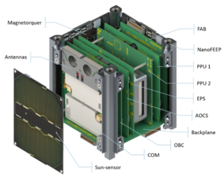
The UWE-4 satellite is based on the architecture introduced by UNISEC Europe which has been demonstrated first on UWE-3. It makes use of a backplane which interconnects all subsystems with a standardized interface and also interfaces the CubeSat’s panels. This architecture supports rapid development, test, and integration of new subsystems. It provides several redundant communication busses (I²C, UART, and MLVDS) and power busses, dedicated synchronization signals, and complete debug access to each subsystem. The subsystem stack consists of the OBC, the Attitude and Orbit Control System (AOCS), the PPU, the Electrical Power Subsystem (EPS), the UHF Communication System (COM), and the Front Access Board (FAB).
On-Board Computer
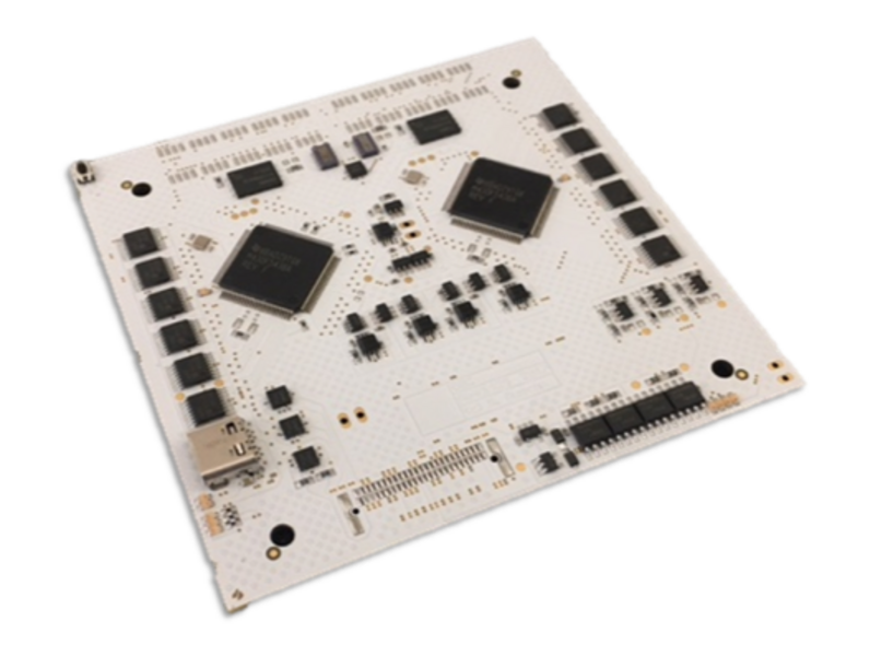
The UWE-4 OBC profits from its heritage of the precursor satellite UWE-3 and was further developed in cooperation with ZfT. It features two redundant low-power micro-processors fully interconnected in order to repair and restore one another in case of radiation induced failures. Both processors are monitored by a watchdog cascade in order to detect faulty behavior. In-orbit operation of the UWE-3 OBC has proven its reliability since launch in 2013. Its purpose is to monitor the overall health status of the satellite and to allow communication from ground with all subsystems through the COM system. Its power consumption of <15mW guarantees that it is always switched on, even in severe low-power conditions. Furthermore, the OBC carries its own latchup-protection with automatic power cycling capability and a backup power conditioning unit.
The new developments focused on an enhanced implementation of the redundancy concept and on extending the system’s debug access to other subsystems. Therefore, the system now carries two independent high precision real-time clocks, employs several independent FRAM chips with a total storage capacity of 40Mbit, a set of 4Gbit NAND Flash memory chips, and a pair of microSD card slots. Furthermore, it implements debug interfaces to all other subsystems’ micro-processors which includes 4-Wire-JTAG and Spy-Bi-Wire (2-Wire-JTAG) for other TI MSP micro-controllers, and Serial Wire Debug (SWD) for support of ATMEL ARM processors. This debug access further extends the system’s capability for fail-safe in-orbit software updates which has successfully been demonstrated with UWE-3.
Attitude and Orbit Control System
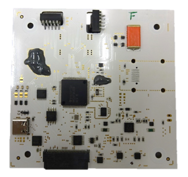
The UWE-4 attitude and orbit control system also inherits its basic setup from the UWE-3 ADCS. It is implemented as standard subsystem carrying a low-power micro-controller (µC) that fuses sensor data from magnetometers, sun-sensors, and gyroscopes, and computes attitude and orbit control outputs for the satellite’s magnetorquer and propulsion system.
The sensor suite is enhanced with respect to the UWE 3 ADCS but the original sensors have been kept as backup. The µC now has access to a primary highly integrated MEMS 9-axis IMU (each 3-axis magnetometer, gyroscope, and accelerometer) placed on the AOCS board itself as well as a set of secondary magnetometers and high precision gyroscopes. Each CubeSat panel carries a redundant IMU and a high precision sun-sensor. All sensors’ data can be injected into the Kalman filter sequentially and independently, such that a coarse attitude determination is also available during eclipse.
The sun-sensors are based on an ultra-low power miniature CMOS camera with a field of view of more than 90deg at 250x250 pixel resolution and nominal power consumption of only 4.2mW. Preliminary calibration results indicate that a sensor accuracy of better than 0.1deg is achievable and an accuracy of down to 0.01deg might be achievable in the future.
Attitude control is performed with the help of magnetic torquers and the propulsion system. The torquers are placed on each panel with a total magnetic moment of 0.1Am² per axis and are mainly used for angular rate control. The four thrusters are used for precise thrust axis pointing. Although the thrusters can only exert a weak torque of up to 1µNm each, the limited magnetic controllability of the satellite is completed and simulations show that a thrust vector pointing is feasible. The hybrid attitude control algorithms are tested in a simulation previously verified against in-orbit data from UWE-3.
Special care has been taken in order to minimize the satellite’s magnetic dipole which has been a major disturbance of the UWE-3 attitude control efforts. As such, the CubeSat’s antenna material has been exchanged for CuBe and the main structural components are manufactured from aluminum or titan.
The attitude determination system also plays an important role in the accomplishment of the technical mission objective. Since the electric propulsion system produces very small thrust levels in the µN range its precise characterization is difficult to achieve via an orbit determination process. However, even very small torques on the satellite are measureable by the attitude determination system as shown during the UWE-3 mission. There, the residual magnetic dipole moment was estimated by analysis of the passively acting magnetic disturbance on the satellite’s dynamics. The measured torque levels also are between 0.1µNm and 5µNm and vary according to the satellite’s motion with respect to the Earth’s magnetic field. The thrusters, however, generate a torque that is time invariant in body coordinates and consequently even better to distinguish from noise and also other perturbations. Therefore, the same algorithm used in UWE-3 for estimation of the residual magnetic dipole will be used in UWE-4 for precise thrust estimation of each thruster.
After having accomplished the primary technical objective of thrust estimation and determination of the operation characteristics of the propulsion system, the goal is to perform basic orbit control maneuvers. For this, the satellite will point its Z-axis (thrust vector axis) in in-track direction and thrust in vicinity of the orbit’s apogee. This will slowly lower the orbit and will be visible in orbit estimation data from NORAD thereafter. Simulations show, that by this technique a perigee lowering of about one kilometer per week is feasible. In future applications, such as the formation flying mission NetSat by ZfT, the propulsion system will give 1U CubeSats a total maneuvering capability of up to v = 60m/s.
Electric Propulsion System
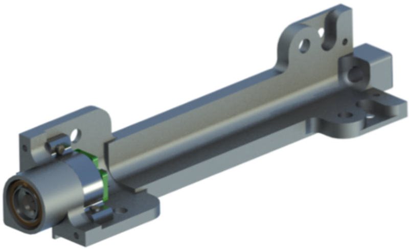
The electric propulsion system acts as the technical payload of the UWE-4 CubeSat. The NanoFEEP system developed at TU Dresden was selected for its compatibility with the 1U size and power restrictions. The system consists of the thruster heads and two dedicated power processing units. The thruster heads have been integrated into the CubeSat bars, while the PPUs are designed as standard subsystems for the UNISEC Europe bus.
The thrust is generated through ionization and subsequent acceleration of small amounts of Gallium fuel. The fuel is stored in the thruster heads (0.25g each) and is heated to a temperature of about 50°C at which the Gallium is liquid and flows due to capillary forces along the porous needle to its tip. An electric voltage of up to 12kV between the needle and the extractor cathode ejects the ions from the thruster by electrostatic force. The ejection of purely positively charged ions would change the satellite’s potential. When the voltage between the satellite and the surrounding space plasma becomes sufficiently large, a spark could be created and harm the satellite. Therefore, UWE 4 is also equipped with two redundant neutralizers. These are made from carbon nanotubes which are grown on a substrate. If an electric voltage of up to 3kV is applied between the substrate and an extractor cathode, electrons are ejected. The required voltage is generated from the unregulated battery voltage on one of the two PPUs which can provide up to 250µA of current. Each PPU can interface and power two thruster heads and one neutralizer individually. A single thruster can generate continuously a thrust level of up to 8µN with peaks up to 20µN and requires approximately 700mW at 2µN thrust.
Besides its application in the field of formation flying of CubeSats this flexible and modular propulsion system could in future be used for precise attitude control and orbit maintenance of lower Earth orbits.
Communication system
For communication with ground the flight proven UHF communication system from UWE-3 is employed with only minor modifications. It has shown its robustness and endurance in more than 5 years of in-orbit operations and is still in best health condition.
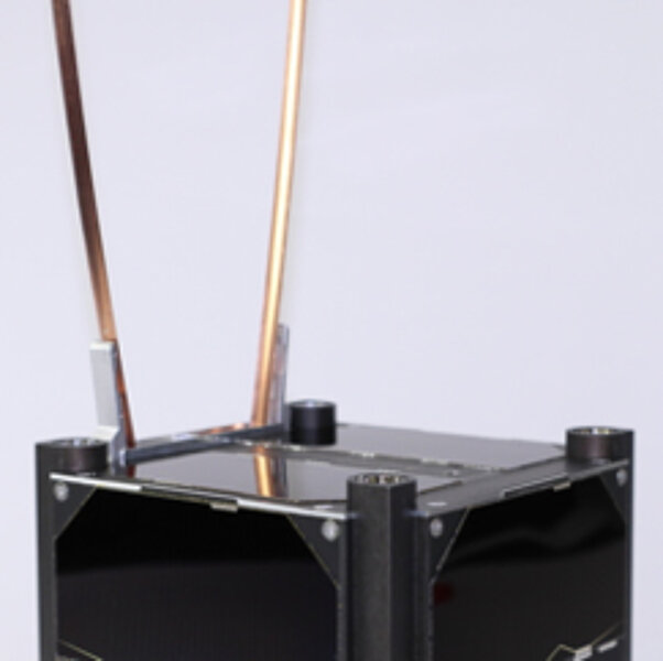
The COM system is built from two redundant Li-1 UHF transceivers each interconnected to its own /4-monopole antenna with all components placed on one subsystem board. The antenna deployment system is a reversible, non-destructive mechanism that has proven its fitness in numerous tests before launch and through faultless operation in-orbit. Each of the transceivers is connected to the OBC by a dedicated UART interface such that a completely redundant system is obtained.
The antennas of UWE-3 have been found to be the most probable cause for its residual magnetic dipole moment. As for many other CubeSats these were made from stainless steel measuring tape. In order to avoid this influence on attitude control the UWE-4 antennas are made of CuBe.
Electrical Power System
The EPS of UWE-4 has inherited its distributed architecture from UWE-3. The solar cells’ power is directly tracked on each panel and supplied to the batteries. The EPS board itself carries two redundant 2.6Ah Li-ion batteries and several power conditioning units for the regulated 3.3V and 5.0V power busses. Power distribution is realized through the standardized subsystem interfaces which are controlled through the OBC. The batteries are monitored and protected against low voltage conditions and the power conditioning units passively distribute the actual power demand among them. The satellite’s power busses can be generated by one of the two power paths (battery & power conditioning units) or both in parallel for power demanding applications. The standardized subsystem interfaces provide power monitoring, latchup-, over-voltage and under-voltage protection for each subsystem individually.
With respect to its predecessor system only few changes have been applied to the UWE-4 EPS. One is that new analog Maximum Power Point Tracking (MPPT) electronics are placed on each panel for improved voltage stability at each cell’s optimal operating point. Furthermore, the power switching of the satellite has been revised and the changes made will further enhance the overall satellite efficiency.